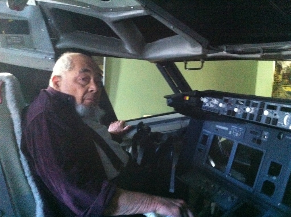
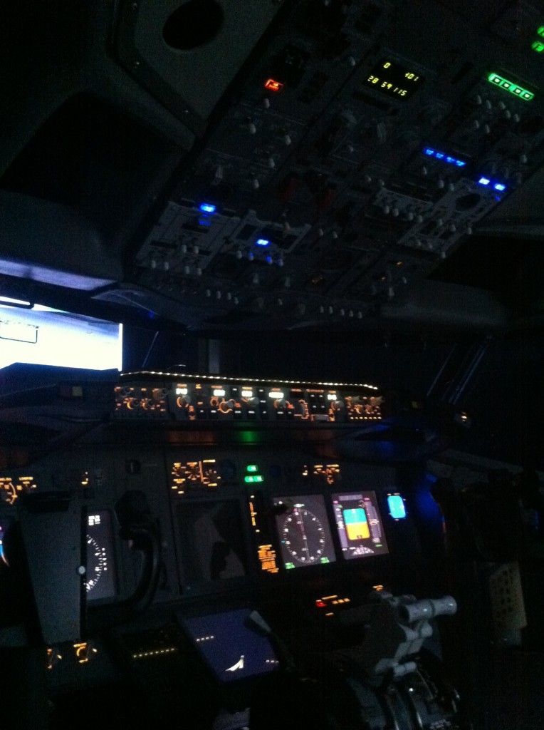
In late October my wife and I finally moved into our dream house: a place big enough for our menagerie of two dogs and two cats, with ample room left over for the ultimate man cave: a full size, fixed-base Boeing 737 simulator in the basement! Unfortunately all the tasks associated with moving brought progress on the sim to a grinding halt for close to six months.

I did manage to bring home most of the gear I had acquired prior to taking the major leap of buying an entire nose section. I set this up in the basement with the idea of making an avionics test bed for the additional real Boeing parts that I continue to find on eBay and other internet sources. The dual-linked flight controls, throttle quadrant and projection screen were made by Art May-Alyea of Northern Flight Sim. I had a steel frame made at my local metal fabricator that allowed me to hang the overhead panel in the proper position on the ceiling. It’s not flying yet, but I will need to get it running soon, as I just acquired a real fire control panel and other real parts that need to be interfaced.
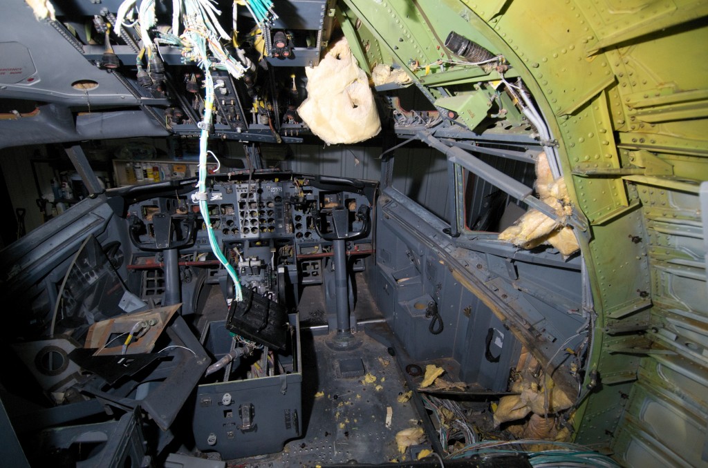
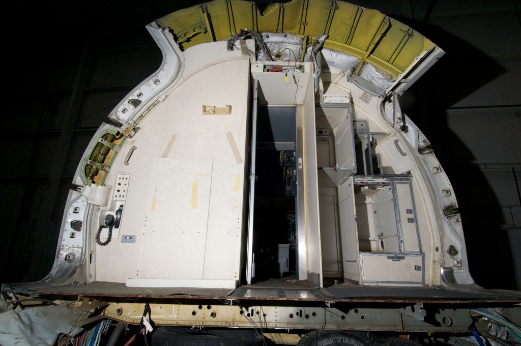
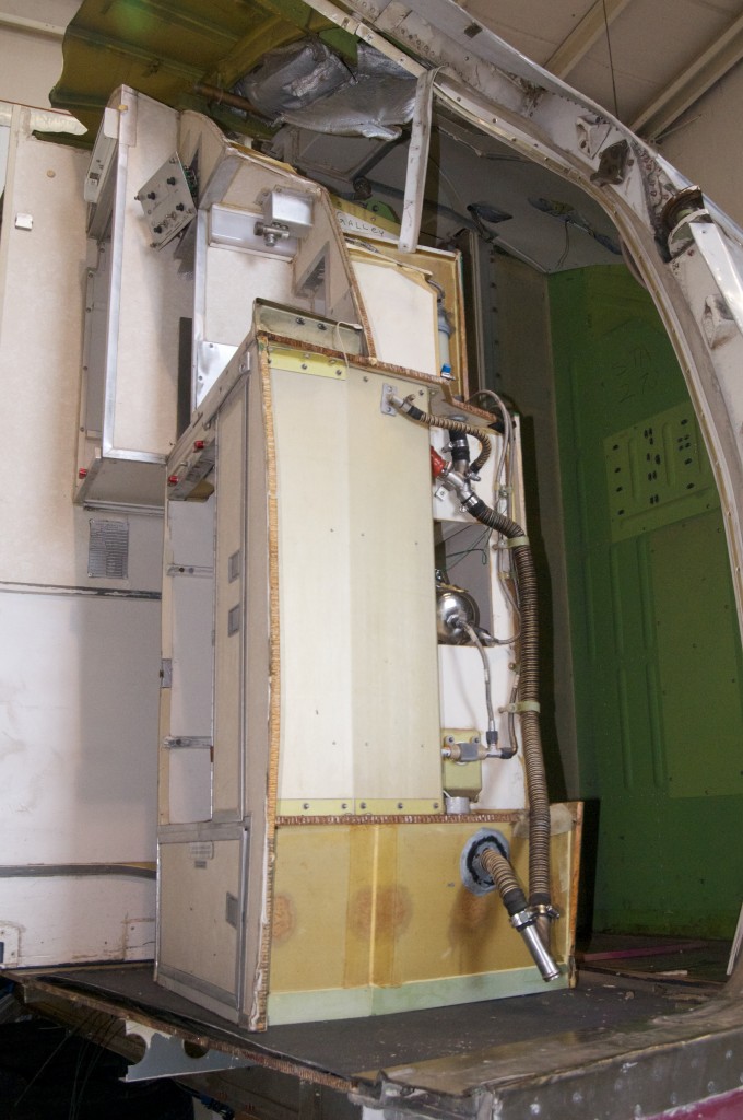
The nose section of N332UA still sits out at the airport, where I continue to remove parts from the interior in anticipation of cutting it into sections small enough to fit through the standard residential door of my walkout basement. The galley was easy enough to remove, as it is essentially a single assembly bolted to the floor, and attached to the top of the airframe by only one large pin. Removing the plumbing and electrical connections was relatively easy, especially compared to removing the lav on the captain’s side. The walls of the lav were bolted to the floor some 24 years ago, and almost every fastener was stuck enough that removal required drilling. A side benefit was that I finally figured out how to use those damaged screw removal kits they sell at Sears.


The disassembly phase continued to the wall of circuit breakers behind the first officer’s seat. For better or for worse, I had seen a really cool video online showing how the interior of the 737 is installed, and it was very clear (see it at 0:25 into the video) that the structure housing the circuit breakers was an assembly that rolled in and bolted to the airframe. While it was probably made to be easy to install, it was never intended to be removed and it took a couple of days of removing wire bundles, ducting and insulation before I found all of the fasteners holding it in place. There was also quite a bit of head-scratching and occasionally swearing. Several times I was certain I had found all the screws and bolts but a vigorous shaking only revealed that it was still attached somewhere. It finally came loose and fell backwards onto the floor, with a very satisfying thud and a genuine feeling of progress.


The wall behind the captain’s seat consists of a much smaller circuit breaker assembly, as well as a wall and a jumpseat. If anyone ever had the idea of burrowing through the front of the first class lav to break into the cockpit in flight, let me just say that it’s never going to happen!

